How Are Nozzles-case-study-banner

How to Size Nozzles & Determine Protection Needs for Heat Exchangers

how are nozzles sized

How to Size Nozzles & Determine Protection Needs for Heat Exchangers

You may have wondered how nozzles are sized for heat exchangers – why are some 12 inches in diameter while others are 4, 6, or 24 inches?  Well, it mostly comes down the how much flow is going through them.  Higher flows need larger diameter nozzles – not unlike a four-lane highway vs a side-street. 

In general, our customers specify the nozzle size they need to match their piping, but we also need to check this sizing during our thermal design to ensure nozzles are big enough. 

how are nozzles sized
flow velocity

If the nozzle size is too small, the fluid velocities inside the nozzles can become very large and will cause erosion at the nozzles, nozzle interface to the shell cylinder, and to the tubes themselves. This kind of damage is a common reason facilities require heat exchanger repair to restore performance and prevent further degradation. In the picture to the right showing a narrowed pipe, the flowrate is the same from left to right throughout, but you intuitively know that the velocity in the middle ‘pinched’ section will be much higher.

Undersized nozzles also cause more pressure-loss through them, which costs energy in terms of more pumping power required, but also less opportunity for us to optimize the heat exchanger design for heat transfer.

Choosing nozzle sizes by the amount of flow is not accurate enough – there are too many different types of fluids in both liquid and vapour states, so we use a formula known as  (pronounced rho-vee-squared).

What this formula means is we take the process density (rho) and multiple it by the velocity (v) twice. We would already know the density because the customer provides us that along with the flowrate, but do need to calculate the velocity ourselves (next page).

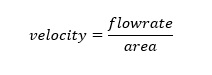
Fluid velocity inside a nozzle is calculated from the flowrate divided by the cross-sectional flow area of the nozzle:

velocity-formula

…but we don’t have the area yet you say?  Well, to get the nozzle (flow) area, you may remember this one from grade school:

area-of-circle-formula

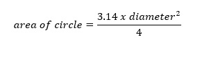
Alright, now we can do some math. I will assume nozzle size is 12 (ignoring units):


Area = 3.14 x 12 x 12 divided by 4
Area = 113


Now we can jump back to the velocity equation, and assuming flowrate is 500 (ignoring units again):


Velocity = 500 divided by 113
Velocity = 4.4


However, if we use a smaller nozzle size like 4, instead of 12:


Area = 3.14 x 4 x 4 / 4
Area = 13

Velocity = 500 divided by 13
Velocity = 38.


Hopefully, everyone is still with me here – we are heading into the final stretch.  Now, using water with a density (rho) of 62, the rho-vee-squared values can be calculated for both the 12 and 4 inch nozzles.


12 inch nozzle, rho-vee-squared = 62 x 4.4 x 4.4 = 1,200

4 inch nozzle, rho-vee-squared = 62 x 38 x 38 = 89,528


The rho-vee-squared numbers above are essentially showing how energetic the flow is through the nozzles, and you can see that the smaller 4 inch nozzle has a value about 75x higher than the 12 inch nozzle.


So how do we know if a rho-vee-squared number is safe? We reference the TEMA (Tubular Exchanger Manufacturers Association) handbook (section RCB-4.6) for suggested values:

RCB-4.6

What Are Nozzles and Their Functions in Heat Exchangers

In a heat exchanger, nozzles are the critical inlet and outlet connections that allow process fluids to enter and exit the equipment. They serve as the interface between the exchanger and the piping system, directing fluid flow into the vessel while controlling velocity and minimizing turbulence-related damage. A properly designed heat exchanger nozzle ensures uniform flow distribution across the tube bundle or plate pack, which directly impacts thermal efficiency and mechanical longevity. According to TEMA Standards, nozzle sizing and placement are fundamental to preventing flow-induced vibration, localized erosion, and thermal stress.

Beyond simply acting as flow ports, nozzles also provide structural support for accessories such as impingement plates—protective baffles designed to prevent high-velocity fluid streams from damaging internal components. In high-pressure or abrasive service, material selection for the nozzle is as important as its geometry, with stainless steels, nickel alloys, and wear-resistant claddings often specified to extend service life.

Standard Nozzle Dimensions and Industry Guidelines

The standard nozzle dimensions for a heat exchanger are typically defined by project specifications, TEMA guidelines, and applicable ASME codes. These standards ensure compatibility with existing plant piping, flanges, and maintenance procedures. In many cases, a standard sized heat exchanger will feature nozzle diameters aligned with ANSI/ASME B16.5 flange sizes, simplifying installation and replacement. Nozzle neck length, bore diameter, flange rating, and reinforcement pad thickness are all determined based on fluid velocity, operating pressure, and allowable stress for the selected material.

For industrial designs, maintaining correct nozzle proportions is critical to balancing pressure drop, erosion resistance, and flow uniformity. For example, undersized nozzles can cause excessive velocity, leading to erosion at the inlet, while oversized nozzles may create poor distribution and dead zones inside the exchanger. By following industry guidelines such as those from ASME Section VIII and TEMA, engineers can ensure their nozzle design supports both process performance and long-term heat exchanger protection.

To download your free copy of the Specialty Service Brochure, please enter your name and email.

To download your free copy of the Air Cool brochure, please enter your name and email.

To download your free copy of the guide, please enter your name and email.